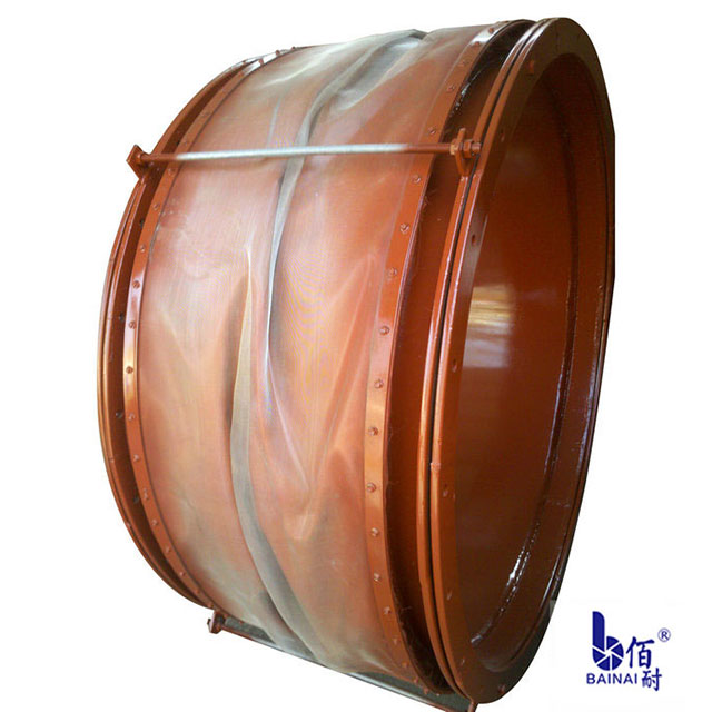
) to determine whether expansion joints are required for pipe sections.
1. We know that. One is the equipment parameters (provided by the equipment drawings). Equipment nozzle: 1DW K2726RF end allowable load, FX=210. OOF/KN, FY=150. F/K N, FZ=220. O0 F/K N. Second, pipeline parameters. According to the design temperature and pipeline material, according to section 6.1.1 of the M aterial database of PipingStress Ana lysis () document of taishan project and section rccm-c, the allowable thermal stress of this pipe segment is 162.00m pa.
2. Calculate the thermal stress of the pipe section and the stress at the equipment interface.

(1) calculate according to the situation that expansion joints are not set. This stress calculation only considers the secondary stress calculation, because the primary stress calculation is mainly to calculate the stress caused by the earthquake load, and has no influence on the secondary stress calculation, which can be assumed to be verified, and the secondary stress calculation is mainly to calculate the stress caused by thermal expansion. After SYSPIP234D calculation, the thermal stress of the device interface (node 1) and pipe segment (all other nodes are pipe segment nodes) is shown in the thermal stress calculation table, which is omitted (note: except the endpoint, other nodes have left and right units, and the unit value is not necessarily the same.) According to the calculation data of SYSPIP234D, the thermal stress value of the right element of node 1 and node 2 is greater than the thermal allowable stress 162. OOM pa, mechanical calculation cannot pass. The mechanical analysis is carried out on the interface of the equipment, and the results are shown in the mechanical report data, which is omitted. It can be seen from the mechanical report that the force in the x and Y direction is greater than the allowable load at the nozzle of the equipment, namely 539. O0 > 210. 004, 549. O0 > 150. 00. If expansion joints are not set, the force on the nozzle of the equipment cannot pass through.
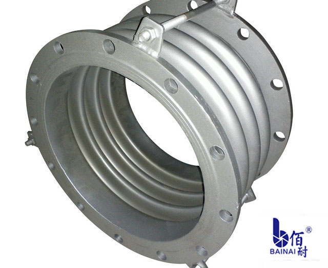
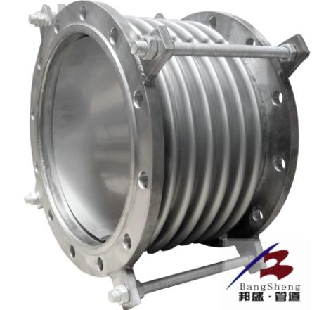
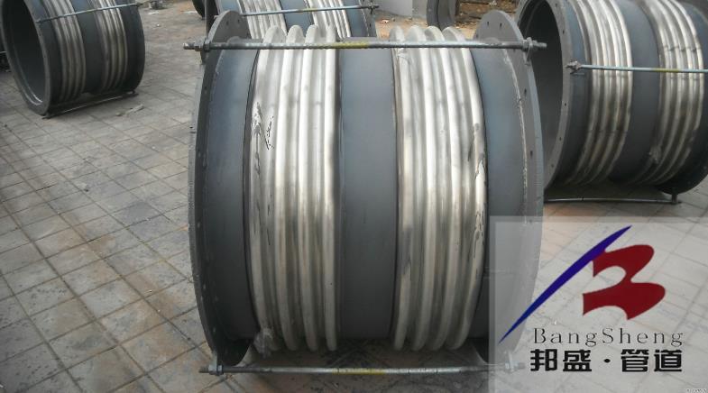
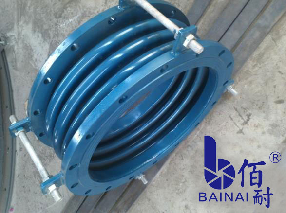
(2) calculate according to the setting of expansion joint. First, set the expansion joint of the pipe section as a rigid unit that can release six directions of force. Then, the thermal stress value of each node was obtained through SYSPIP234D calculation. It can be obtained from the thermal stress value that the thermal stress value at each node after setting the expansion joint is less than the thermal allowable stress value, and the calculation result can be obtained through. At this time, mechanical analysis is carried out on the interface of the equipment. It can be seen from the data that after the expansion joints are set, the force values in the X, Y and Z directions are within the allowable load range of the nozzle of the equipment, and the calculation results can be passed. According to the characteristics of this end section and the size of the space in which the section is located, choosing bellows expansion joint is an economical and reliable method.
(2) determine the type of expansion joint. According to formula (1), the thermal displacement at the interface of the equipment is as follows: U X=D X X ding X A T=362 X 11. 50 X 10 X(60-2O)=16. 65 m m; U Y=D Y staring at X delta T=(1 423) 11. 50 times 10 times 60 -- 20 is 1 19. 55 r a, m. U, Z: D, Z, X staring at X, A, T=(1, 475)X, 11. 50 times X 10 times 60 minus 20 is equal to 1, 21. 85 m m; R, X is equal to R, Y is equal to R, Z is equal to 0. 0 0. (note: D X, D Y, D Z are measured in PD M S. R refers to angular deflection displacement, and the additional displacement of the device endpoint is the displacement relative to the fixed point of the device. A negative value is the inverse of an axis. According to formula (2), x = only LX x A T=l1 for this segment in the x direction. 14 x 10 x 458 x (60 -- 20) : 20. 41m m, Y direction delta Y=0lT LY A T=11. 14 X 10 X(1 139) X(60 -- 20) : 1 6. 19 m, m, A, Z is equal to 0. O0. The heat displacement in the x direction of the system is 37. 06r a m, the thermal displacement in the Y direction is one 25. 74r a m, the heat displacement in the Z direction is one 21. 85 m m. After analysis of displacement data, the expansion joints of bellows that can absorb displacement in x, Y and z directions at the same time only have single universal hinge type.
Determine the number of expansion joints. (10 305/2) (~ / 180)=26, according to formula (6) and parameters provided by the manufacturer. 62 m m > 25. 74r a m, so an expansion joint can meet the absorption requirements. (4) verification after type selection. The parameters after type selection were input into SYSPIP234D, and then the thermal stress of each node was obtained. It can be seen from the data that after setting the expansion joint of single-type universal hinged bellows, the thermal stress value at each node is zero, indicating that this expansion joint can fully absorb the thermal expansion of the pipe segment, and the selection is reasonable. After selecting the type, mechanical analysis was carried out on the interface of the equipment. According to the results, only Z thermal expansion force existed and the value was small after setting the expansion joint of single-type universal hinged bellows. It shows that setting this type of expansion joint has obvious effect on reducing thermal expansion force at the interface of equipment, and the selection of type is reasonable.


